Tuesday, June 23, 2009

DAY 17

Today, Pat Callahan went over design options and third party software.

  Design Options

Design Options help to Schedule, Quantify and Visualize different designs within a building

Schedule – In order to provide a comparison of two design options, you can schedule both options and have a comparison of costs, materials, and labor in order to give the client a better idea of what goes on in the design

Quantify – Like scheduling, you can account for exactly what you need and how much you need of it in order to implement the different designs

Visualize – Main element that the client will be interested in, in seeing the different designs and being able to compare them

Third Party Software

Third party software are the analysis tools which takes databases produced in Revit and analyzes that information.  Especs is the software which takes information from Revit to compile the Specs of the project. Innovaya is the cost estimating software which utilizes types and amounts of materials in order to produce a cost estimate. There are also programs which compute energy analysis, structural analysis, and mep analysis. 


Monday, June 22, 2009

Day 16

Today in class, Shane Gray and Elizabeth Veatch talked about linking files into a Revit project.  We also got a chance to learn about massing from Craig. 

Linking Files

-linking is the process of importing a revit project into another called the host file

-control visibility through a host’s visibility graphics – the Revit Links button on the top of the page allows you to control the visibility graphics for each individual link – click on By Host View of the Linked document to change how it is seen

-in order to change anything in the linked files, you must close the host view, make the change in the original document and reload the link into the host project – this can be done by going into file, manage links and clicking the reload button

-when making schedules ensure the option “include elements in linked files” is checked

Massing

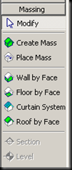
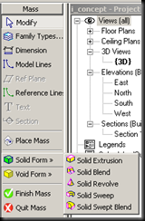
image-two different ways to make masses

creating a mass – created using the solid and void forms in order to create custom 3d objects

placing a mass – utilizes pre-defined shapes in order to create massing forms, good for use in conceptual work

-the wall by face, floor by face, curtain system by face, and roof by space allow you to select a massing and associate it with building properties…for example making a mass become a wall, you would click on the wall by face and then select the type of wall you want the mass to be and define it-helpful tool when transforming conceptual into a defined form

-creating a mass-utilizes different sorts of tools in order to manipulate 3d geometry

solid extrusion-takes a face and extrudeimages it

solid blend-draw the top and bottom, or side to side profiles and it creates a custom form between the two profiles-used for geometric forms

solid revolve-creates a mass by taking a profile and rotating it to define its path

solid sweep-like the solid blend, used for organic forms, where a profile is connected through a defined path

solid swept blend-like the solid sweep, except there are two profiles in which need to be defined as well as their extrusion path


Thursday, June 18, 2009

Day 14

Today, Adam Wallen taught us the fundamentals behind Families, in particular in door families.

Fundamentals of parametric families

Create reference planes to constrain family elements

For door and window families, make sure the opening cut is large enough to encase your family (to get to opening cut go to the edge of the family and press tab until you get it)

Add parameters to dimensions to make family types

When family utilizes parameters effectively, the family can be scheduled

WORD OF WISDOM FROM PAT CALLAHAN

Before beginning a family think about what you want to accomplish when building the family.  This may require you to constrain proportions of different elements in the family or create parameters for those elements.  Think about how one element needs to move with its hosting element and how you can accomplish that.

Wednesday, June 17, 2009

Day 12

Boot Campers

revit bootcampers - we are really really good looking

Today in class, Mike Padavic and Michael Herdegen taught the bootcampers about sloped roofing, flooring, and slabs and furthered our knowledge about how to create curtain walls in Revit.

Sloped Roofs, Floors, and Slabs

WHY? To follow site work, control drainage

HOW? Slope structure or taper insulation

The method to sloping floors, roofs, and slabs is the same, so you can apply the steps below to any of these. 

  1. Create the element as you normally would
  2. In a floorplan view, look to the options bar to find this toolbar. This allows you to split the surface you have created and add reference points in order to create the differences in elevationsimage  
  3. In order to get your desired effect, you will have to play with some of the options above, but in order to give an example, we will create a roof which is sloped 
  4. The roof is already made, so the next step is to add valleys in order the split the surface up.  This can be done by selecting the image button.  Draw a line in the areas you want to add valleys or ridgesimage
  5. 5. Once this is done, you can change the elevations of the ridges/valleys by using the image
  6. button and changing the elevation (option give to you on the design options toolbar)

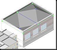
6.  You can also have the slope come to one point by using the imagebutton. This will allow you to define the elevation of one point on the roof and have the rest of the enclosed portion follow

image

image


effect of defining ridge              effect of defining point elevation                                 elevation

This process is the same for floors, slabs and roofs, so play around with the options to get the desired effect.  If you need a path to follow contour marks, however, you may also define that path’s slope in the site menu.

Curtain Walls

guidelines for creating curtain walls

  • to create custom profiles for mullions, create a new family of mullion and load into the project (you can also insert details components into the projects this way)
  • to put in a curtain wall door, select the panel in which you want to place the door, and select the door out of the wall menu (door not found in doors tab, but found where the curtain wall and curtain panels are)
  • to create a curved curtain wall, draw the curtain wall with the curve tool and place mullions (if you do not place mullions, the curtain wall will appear straight…mullions give the curtain wall its curved shape)
  • you can select different pains of glass and turn them into walls or panels in order to vary the curtain wall’s appearance
  • in order to create a curved curtain panel, create a new panel family and draw out the curve with the solid extrusion tool then load the new panel into the project…select the panels which you want to be curved and change their properties from the curtain panel to the curved panel in the type menu

Day 13

Today, Pat Callahan taught us how to work incorporate topography into a site and about how important collaboration between consultants and architects is and how Revit can assist in the flow of information. 

Site Topography

Background: The relationship between a building and the ground line is extremely important, as it establishes how a building sits in an environment, how the foundation is seen, how a “balanced site” is achieved, and how building is successfully incorporated into an environment.  The technology we have today to map contours allows the architects to get a 3d image of the site, through a GPS system which plots points throughout the site translated into an ASI file.  An ASI file can be brought into Revit, and because the plotted points have an x, y, and z coordinates, we are able to view a 3D model to which we can better incorporate a building into.  This new technology adds a better understanding of the site in much less time than in previous years. 

How to use an ASI file to create site topography:

image

  • To import an ASI file, go to import, CAD formats, and choose your file.
  • To create a toposurface from scratch, go to the design bar, click toposurface and then click point. Set different elevation points according to the site surface, and click finish when you are done.
  • In order to edit the topography, you have a number of tools at your hands in order to get the look you want to achieve.
    • Visibility graphics: in the visibility graphics dialogue, you can edit boundary points, interior points, primary and secondary contours, and triangulation edges in order to change the way you view element of the topography.
    • Site Settings Box (under settings menu): you can edit property data, with different property lines, angular values, or bearing values. Also able to edit section graphics of the site.

image

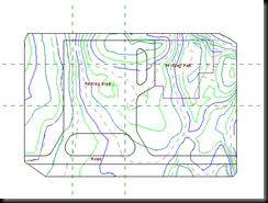
    • Splitting Toposurfaces: in the design toolbar, you are able to edit different surfaces within a toposurface. In the site shown above, you would split the site boundaries from the parking lot boundaries, island properties, and building pad.  This allows you to dissociate the areas from the original toposurface and edit them individually.
    • Merging Toposurfaces: in the design toolbar, you are also able to merge regions if they have common edges or overlap in any way.

image

Site Tools

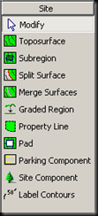
Subregion: subregions are isolated regions sketched on a toposurface which can be associated with different materials  and elevations.  This can be put in by sketching it on the toposurface.

Graded Regions: method to create elements like parking lots, where you extract an area from the toposurface and change its elevations and properties.  When you create a region, the cut region is shown is translucent graphics, and you will be able to view the cut and fill volumes in order to modify the surrounding landscape.

Property Lines: the legal boundary lines of a property which are created with fixed distances, angles, and directions in the site settings box.

Pad: vertical cuts in a toposurface that represent excavations and slabs.

Site Components: In order to complete the site you are able to insert site components like trees, shrubs, parking spaces, parking islands, utility poles, vehicles, etc.


Importance of Collaboration

Revit is the new technology creating a way for different professions to have an entirely new way of communicating with each other: in 3 dimensions.  There are three Revit programs: Revit Architecture, Revit Structures (which is also built into Revit Architecture), and Revit MEP (which is a separate program used for mechanical, electrical, and plumbing).  The collaboration of these three programs along with outside analysis programs like Innovaya, IES, Navis Works, Green Building Studio, etc..  Elements in Revit like family components, schedules, details, and area plans enable architects to communicate better with consultants and clients, which inevitably will result in more efficient buildings.

Monday, June 15, 2009

Day 11

Today in class, Angie taught us bootcampers about Exporting Files and Energy Analysis Modeling. 

Importing/Exporting Files

In the file menu, under export, there are a number of options in which you can export a Revit model into a format to which a third party can work with. 

image

CAD Formats – exporting into a format that AutoCAD products can read

Walkthrough – this menu gives you the ability to export a walkthrough into a video format

Animated Solar Study – this is just like a walkthrough with emphasis on path of light

Image – exports view into an image format

gbXML – exports the file into a format that an energy analysis program can read

Room/Area Report – provides a report of the area and volume of rooms – helpful for energy analysis models

3ds Max (FBX) – this setting exports the BIM model in 3d form to a format 3d studio max can read.  It imports materials and components, but you need to place your own lights


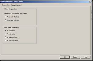
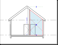
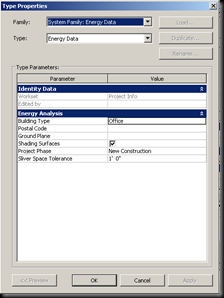
The gbXML format is used for energy analysis programs like Autodesk’s Green Building Studio and IES.  This is much like rendering, in that you want to limit what you are rendering to make the process as uncomplicated as possible. For this format, you may only need to export walls, windows/doors, flooring, roof, and room tags.  For this to work, you need to go to make sure area/volume computations is checked under the settings area/volume box.  You also need to extend the room boundary up to the roof as shown below.  Under project information in the setting tab, you need to go into Energy data and input the building type and postal code so that the energy program can process the building.  

image

image image

Once in the energy analysis programs, you need to input some of the need data, like construction method, type of curtain walls, etc. in order to obtain the correct information about the building.

Friday, June 12, 2009

Day 10

Today in class, Adam Wallen taught the bootcampers about working with groups and linking models. 

Groups

To group components together, highlight the ones you wish to group and press group on the edit bar.   image

That will bring you to a model group bar in which you can edit the groups any way you would like. image

For Material Take-off schedules, go to view--->new--->material takeoff and that will enable you to choose the type of material schedule you would like to create.  From there use the fields in order to break down which categories you would like to include in the schedule.  Once you create the schedule, you will need to populate it with the needed information in order to finish it.  If you go to element properties, it will give you the option to get to the window below in order to edit the schedule.  Besides adding fields, you can also add parameters about any components of the list as well as create a series of filters and formats in order to help organize the schedule better. 

image

Importing/Exporting CAD formats

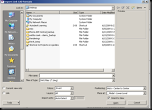
In order to import a CAD file, go to file--->import--->CAD formats.  Here you will be able to decide how you would like to view the imported CAD file.

To Export into Cad go to file --->export--->cad formats.

imageManipulating CAD Images

In order to manipulate the cad file, go to the options bar at the top and you will be able to adjust whatever you would like. DO NOT EXPLODE A CAD FILE. The query command allows you to edit the image as you need to by allowing you to delete or hide some elements.

image

Linking Files

In order to Link files to one another, as in the case of linking structural or electrical files to the BIM model, go to file ---> import/link Revit.

Managing Views

In order to manage your views of linked files, go to visibility graphics and go to the Revit links.  Here you will be able to view and update Revit Links that you have in your file. 

Thursday, June 11, 2009

Day 9

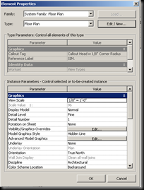
In today’s lesson, we learned about the visibility graphics in Revit from the head honcho of Revit, Craig Meadows.  We also got a chance to work with legends and schedules.  There are a number of ways in which you can control the view settings in Revit: through the view toolbar on the bottom of the page, through view properties, or through visibility graphics.

imageThis toolbar on the bottom off the page contains a lot of the same things that view properties does in a convenient toolbar.  It contains the scale, level of detail button (course, medium, or fine), display graphics (wireframe, hidden line, shading, or shading with edges), shadows button (which can slow your computer down if turned on all the time-use on a need basis), crop regions, temporary Hide, and a reveal hidden objects bar.  Before getting into a project, a good method is to get used to these settings and decide personal preferences regarding viewing your project.
image

image


image

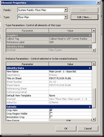
The view properties toolbar allows you to change some of the same types of things but also offers you options on how to use an underlay, extents, phasing, and much more. To get to this menu either right click on the view or type vp.  An underlay is an option you can choose if you wish to see a floor plan on another one, like if you are on the bottom floor and want to see a grayed out version of the top. In extents, you can manage the view range, or the ability to change the extents of a certain view.  The scope box is a way to take a 3D view and make only show portions of the drawing.  You do this by positioning the box so that the element you want to see are in the box and the ones you don't want to see are not.  This works great for 3D floor plans or axonometric sections.

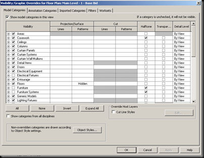
The visibility graphics is a way to control what and how you see elements in the view.  The quick way to get to this menu bar is to type vg.  The checkmarks along the left side of names of elements controls whether or not elements are to be shown in the view.  In the model categories bar, you can control how model elements are shown.  In the annotation categories, you control how annotation and dimensions are viewed.  In imported categories tab, you can filter which imported files, like dwgs, are shown.  In filters, you can create filters which manage which types of elements can be shown.  And the worksets bar allows you to turn on and off worksets.
image 

Legends are views which can be put into multiple sheets, unlike other views.  In general they are ways to put notes in a consolidated location.  You create a legend by going into view and create new, legend.  When adding in legend components, they are not really components, but rather pictures of the component info.  Legend tags are created by placing a symbol into the legend.  In order to change the legend in any way, you must go to the family editor.

Area schedules are much like room schedules.  They can be very important in the integration of program requirements, configuration of cost of building based on cost per square inch, or in indication of spacial requirements. 

Material takeoff schedules pulls information from the project about the types of materials being used and is very helpful in computing material costs, quantities, and other helpful information. 

Schedules allow a user to create a database of information drawn from the model in order to input it into third party programs or in order to compute necessary information about the project, which reduces amount of computing time.